Journal of Applied Science and Engineering

Published by Tamkang University Press

1.30

Impact Factor

1.60

CiteScore

Saranjit Singh This email address is being protected from spambots. You need JavaScript enabled to view it.1, A. K. Jha2 and S. Kumar1

1Department of Production Engineering, Birla Institute of Technology Mesra, Ranchi - 835215, Jharkhand, India
2Department of Mechanical Engineering, Institute of Technology, Banaras Hindu University, Varanasi - 221005, U.P., India


Received: June 24, 2005
Accepted: October 11, 2005
Publication Date: December 1, 2006

Download Citation: ||https://doi.org/10.6180/jase.2006.9.4.03  


ABSTRACT


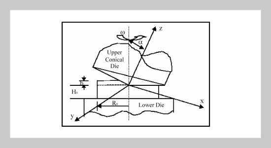
Sinter rotary forging is one of the prominent sinter forming processes, where a fixed bottom die and a moveable/rotating top punch come together to form complex geometric sintered work pieces having high dimensional and shape accuracy. The decisive factors are density of preform, lubrication conditions at die-work-piece interface, flow stress of sintered material and factors related to forging equipment such as axial and angular speed and contact time under load. The sinter rotary forging technique is advantageous than conventional sinter forging technique, as the average load required to carry out the deformation is considerably low due to small contact area. In the present paper theoretical and experimental analysis of the indentation of the sinter rotary forging technique using a rotary forging die set having conical upper die and flat lower die has been done. The work includes the estimation of conical contact area indented by the conical upper die over the preform, formulation of velocity field, strain rates, internal energy dissipation, frictional energy dissipation and average indentation forging load during indentation phase of the deformation has been done.


Keywords: Rotary Forging, Sintered Preform, Upper Bound, Indentation Phase


REFERENCES


  1. [1] Cull, G. W., “Mechanical and Metallurgical Properties of Powder Forging,” Powder Metallurgy, Vol. 13, p. 156 (1970).
  2. [2] Shivpuri, R., “Past Development and Future Trends in the Rotary or Orbital Forging Process,” J. Mater. Shaping Technology, Vol. 6, pp. 5571 (1988).
  3. [3] Standring, P. M. et. al., “Theoretical Investigation and Analysis: Powder Compaction and Sinter Forging,” J. of Mech. Working Tech., Vol. 4, pp. 729 (1980).
  4. [4] Kiyota, F. et. al., “Densification of P/M Value Seat by Cold Rotary Forging,” Proc. of 3rd Int. Conf. on Rotary Metal Working Processes, Japan, pp. 101108 (1984).
  5. [5] Jha, A. K. et. al., “Production of Sinter-Forged Components,” J. of Materials Process. Tech., Vol. 41, pp. 143169 (1994).
  6. [6] Rooks, B. W., “The Effect of Die Temperature on Metal Flow and Die Wear during High-Speed Hot Forging,” Proc. of the 15th Int. M.T.D.R. Conference, p. 487 (1974).
  7. [7] Jha, A. K. et. al., “Compatibility of Sintered Materials during Cold Forging,” Int. J. of Materials & Product Tech., Vol. 9, pp. 281299 (1994).
  8. [8] Jha, A. K. et. al., “Forging of Metal Powder Preforms,” Int. J. of Mach. Tool Design & Res., Vol. 23, p. 210 (1996).
  9. [9] Jha, A. K. et. al., “Dynamic Effects during High-Speed Sinter-Forging Process,” Int. J. of Mach. Tools & Manuf., Vol. 36, p. 1109 (1996).
  10. [10] Singh, S. et. al., “Analysis of Dynamic Effects during High-Speed Forging of Sintered Preforms,” J. of Materials Process. Tech., Vol. 112, pp. 5362 (2001).
  11. [11] Singh, S. et. al., “An Energy Analysis during Forging of Sintered Truncated Conical Preform at High-Speed,” Tamkang J. of Sci. and Engg., Vol. 7, pp. 227236 (2004).
  12. [12] Zhang, M., “Calculating Force and Energy during Rotating Forging,” Proc. of 3rd Int. Conf. on Rotary Metal Working Processes, Japan, pp. 115124 (1984).