Journal of Applied Science and Engineering

Published by Tamkang University Press

1.30

Impact Factor

1.60

CiteScore

K. I. Hwu This email address is being protected from spambots. You need JavaScript enabled to view it.1

1Institute of Electrical Engineering, National Taipei University of Technology, Taipei, Taiwan 106, R.O.C


Received: December 26, 2007
Accepted: February 10, 2009
Publication Date: December 1, 2009

Download Citation: ||https://doi.org/10.6180/jase.2009.12.4.07  


ABSTRACT


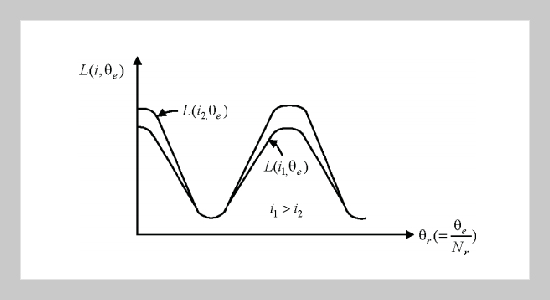
Although PSPICE is a powerful tool to simulate the circuits, it is a tough job to simulate the electromagnetic behavior of a converter-fed motor drive, particularly the switched reluctance motor (SRM) with many nonlinearities in its constituted components. Therefore, a simulation environment of the SRM drive combining the features of POWERSYS and SIMULINK is developed in this paper. In the establishment of SRM system components, the nonlinear inductance-current-position characteristics are experimentally obtained initially. Accordingly, the variation of the phase inductance with rotor position is approximately represented by Fourier series with the first three terms considered. The coefficients of the Fourier series are determined by the values of the inductance at the aligned position, the unaligned position and the position midway between the two. On the other hand, the variation of phase inductance with winding current for a given rotor position is fitted by a third-order polynomial whose coefficients are derived from experimental results. The construction of other components is also described in detail. Furthermore, how to speed up the simulation is suggested. Some experimental and simulated winding current and rotor speed dynamic responses are compared to validate the effectiveness of the developed simulation environment.


Keywords: Fourier Series, POWERSYS, SIMULINK, SRM


REFERENCES


  1. [1] Miller, T. J. E., Switched Reluctance Motors and Their Control, Oxford: Clarendon Press (1993).
  2. [2] Vukosavic, S. and Stefanovic, V. R., “SRM Inverter Topologies: A Comparative Evaluation,” IEEE Trans. Ind. Appl., Vol. 27, pp. 10341049 (1991).
  3. [3] Dessouky, Y. G., Williams, B. W. and Fletcher, J. E., “A Novel Power Converter with Voltage-Boosting Capacitors for a Four-Phase SRM Drive,” IEEE Trans. Ind. Electron., Vol. 45, pp.815823 (1998).
  4. [4] Phillips, N. W., Bolton, H. R., Lewis, J. D., Pollock, C. and Barnes, M., “Simulation of Switched Reluctance Drive System Using Commercially Available Simulation Package,” IEE Conf. Electrical Machines and Drives, pp. 257260 (1995).
  5. [5] Fransceschini, G., Pirani, S., Rinaldi, M. and Tassoni, C., “Spice-Assisted Simulation of Controlled Electric Drives: An Application to Switched Reluctance Motor Drives,” IEEE Trans. Ind. Appl., Vol. 27, pp. 1103 1110l (1991).
  6. [6] Mahdavi, J., Suresh, G., Fahimi, B. and Ehsani, M., “Dynamic Modeling of Nonlinear SRM Drive with Pspice,” IEEE Rec. IAS’97, Vol. 1, pp. 661667 (1997).
  7. [7] Chen, H., Jiang, J., Sun, S. and Zhang, D., “Dynamic Simulation Models of Switched Reluctance Motor Drivers,” IEEE Proc. Intelligent Control and Automation, Vol. 3, pp. 21112115 (2000).
  8. [8] TEQSIM International. POWERSYS Version 2 User’s Guide (1998).
  9. [9] Math Works. SIMULINK Version 1 User’s Guide (1996).
  10. [10] Moghbelli, H. H., Adams, G. E. and Hoft, R. G., “Prediction of the Instantaneous and Steady State Torque of the Switched Reluctance Motor Using Finite Element Method (FEM),” IEEE Rec. IAS’88, Vol. 1, pp. 5970 (1988).
  11. [11] Hwu, K. I. and Liaw, C. M., “DC-Link Voltage Boosting and Switching Control for Switched Reluctance Motor Drives,” IEE Proc. Electr. Power Appl., Vol. 147, pp. 337344 (2000).